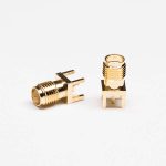
SMA头功率容量怎么看?看看这你就明白了
您对于sma头功率容量知道多少,如果您想了解sma头的功率容量想相关知识,看完这篇稿子就应该差不多了。
同轴电缆/接头功率处理是一个复杂的课题,但它可以分解成两种现象。高峰值功率会导致电弧引起的故障,而高平均功率会导致由于热导致的故障。
射频接头的功率承受与尺寸和材料有关,一般不能直接计算。同一种接头,使用材料不同,功率承受也不一样。
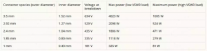
一般来说,接头的功率承受随信号频率变高而降低。对同一频率的射频信号,尺寸大的接头的功率承受大。比如一般的SMA接头,在2GHz的功率承受约为500W,在18GHz下的功率承受不到100W。BMA和SMA差不多,N接头的功率承受约为SMA的3-4倍。以上所述功率承受指连续波功率。如入射功率为脉冲则功率承受还要高些。注意如果传输过程的匹配不好,驻波过大,则接头上承受的功率有可能大于入射功率。一般为安全起见,在接头上加载的功率不应超过其极限功率的1/2。
Peak power handling
This section was greatly improved for August 2017.
Power handling of air coax is a topic that is related to atmospheric breakdown.
Once breakdown occurs, a short circuit is provided across the coax, and Hell breaks loose.
Arcing is caused when the electric field E exceeds a critical value which we will denote Ed for electric field at discharge. In air, the critical field is about 1,000,000 volts/meter, in PTFE it is raised to about 100,000,000. These numbers are approximate, there’s no sense trying to be exact in calculating breakdown, just be sure you avoid it by an order of magnitude or more and you’ll have little to worry about.
The electric field of a coaxial transmission line varies as a function of position along the radial line from the outer conductor to the inner conductor (denoted “ρ” in the radial coordinate system). You’d have to use calculus to derive this, but we just looked it up in Pozar’s Microwave Engineering.
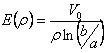
Here, “b” is D/2 and “a” is d/2, the radii of the outer and inner conductors. The peak E-field obviously occurs right at the surface of the center conductor. If this isn’t obvious to you, consider becoming a program manager!

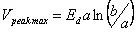
Rearranging the equation for the maximum peak voltage when breakdown occurs,

For fixed “b”, the magic ratio of b/a for highest voltage handling turns out to be exactly “e”, or 2.718… you can prove this easily by taking the derivative of the above equation and setting it to zero (ewww, calculus!) Note that the magic b/a=e ratio for maximum voltage does not change when dielectric is introduced into the coax.
Now, let’s recall a shortcut equation for coax impedance… the “60” in the equation is a close approximation of η0 (the impedance of free space, ~377 ohms) divided by pi. The equation is accurate to at least three decimal places.

At the max voltage condition, ln(b/a)=ln(e)=1. Thus the impedance of air coax that can handle the highest voltage is 60 ohms and the impedance of any coax with any dielectric that can handle the most voltage is 60/SQRT(ER).
The peak power you can put into a coax under well-matched conditions (low VSWR) is calculated from the peak voltage it can withstand:
The 2 in the denominator is necessary because we were considering peak voltage, not RMS.
Plugging the Z0 equation into the Pmax equation yields:
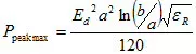
Taking the derivative with respect to “a” and setting it to zero, yields a different magic ratio for maximum power: (b/a) for max power=e^0.5, as opposed to (b/a)=e^1 for maximum voltage. Using the maximum power b/a ratio, you will find that impedance for maximum power is 30/SQRT(ER). Thus, for air coax, Z0=30 ohms optimum for power. For PTFE-filled cables (ER=2.2), Z0 is 20.2 ohms for maximum power.
Now that we have the final equation for maximum peak power handling of coax, we are ready to do some analysis. Remember that this result is only true for a matched load. If you accidentally broke a connection to a high-power transmitter, you’d see a very high VSWR, in that case the peak voltage could double. If you need to consider this type of mishap, you want to further de-rate your power handling by 6 dB.
Now let’s look at some coax examples… how about the air dielectric 50-ohm connectors? The breakdown strength of air 3,300,000 volts/meter according to Wikipedia, but that is at “dry air” at standard temperature and pressure, between spherical electrodes. Let’s use 1,000,000 volts/meter.
How about PTFE-filled coax? The breakdown field strength of PTFE is about 10,000,000 volts per meter! So “049” cable (0.049 inches “D”, 0.015 inches “d”) can withstand 2260 volts and pass almost 50,000 watts peak. This seems to good to be true, doesn’t it? It is. The problem is that with voltage breakdown, the limitation of the weakest link in the chain is what you need to focus on. Your semi-rigid cable might be able to pass thousands of watts, but as soon as that signal crosses a path where the PTFE dielectric fill is interrupted by air, it will spark. At the end of the cable, where the connector is soldered on, there is surely going to be a gap in the dielectric. You need to revise the calculation for air dielectric, in which case you’ll see 256 volts is the maximum voltage, 358 watts is the maximum power into a good load, and 89 watts is the maximum into an unmatched load. Note that at this interface the coax presents 71 ohms impedance.
Before we move on to average power handling of coax, let’s look at power handing as a function of line impedance for air coax, which is part of the “coax compromise” that led to the fifty ohm standard. If you allow the center diameter freedom to move away from 50 ohms, you’ll see that maximum peak power handling occurs at ~30 ohms.
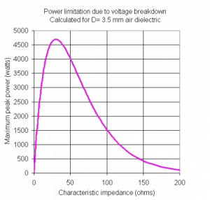
By the way, if anyone wants a copy the spreadsheet that generated this curve, just ask. Eventually we will put it into our download area, it still needs some clean up and comments…
New for August 2017: additional thoughts on this. Peak power handling of air coax may not be at 30 ohms, if you consider another limitation. Suppose you are operating very close to the cut-off of the unwanted TE11 mode. Heck, let’s assume you want to operate exactly at TE11 cut-off. TE11 cuts off when (b+a)*pi is equal to operating wavelength. To cut to the punch line, at TE11 cut-off, 44 ohms carries the most power. You can find this fun fact and many more in Introduction to Microwaves by Gershon J. Wheeler, dating back to 1963.
For September 2017, we created a new page and posted the math behind the 44 ohm absolute maximum peak power handling calculation, it included two solutions: one is brute force, the other is elegant. At least they agree!
Average power handling
Average power causes failure due to heat, as opposed to arcing. Cable vendors provide some guidance on average power handling, but there is a lot of voodoo involved. Basically, you don’t want the center conductor to heat up so much that it compromises the integrity of the cable. In the old days, cable vendors might have derived power handling ratings experimentally.
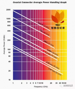
The dissipated power per length is the variable you need to consider, and you will need to note that dissipation is a function of frequency, with the metal loss term being proportional to SQRT(f). Thus, a cable that can handle 100 watts at 4 GHz is only good for 50 watts at 16 GHz.
You must consider how the cable is cooled, i.e. is there forced air, convection, conduction and/or radiation? What is the air temperature? (It can be much higher than room temperature if it is inside a housing or chassis).
If average power handling is a concern, we are going to recommend that you (or someone who knows what they are doing) perform a thermal analysis using finite-element techniques. If anyone has an example average power handling study, please sent it!
本文由德索五金电子运营团队编辑整理,文章来源于网络,如有侵权,请及时联系我们,进行删除。若需采购sma连接器相关产品,请拨打我们的热线电话:0769-81153906,专业工程师辅助您的采购工作。德索五金电子,是一家主做射频连接器的厂家,有着十三年的历史,产品均通过了ISO认证,符合国际上的环保要求,一年内可享受免费质保的服务,欢迎前来采购。